Quadrature FM Detectors


Quadrature FM Detectors
Background
FM stands for Frequency Modulation. It means that the RF-frequency will change acording to the input audio signal.
Example: A FM radio signal at 105.1MHz will not be exactly stable at 105.1MHz, The audio signal in the RF will modulate (change) the frequency for about +/- 37.5kHz. There are some narrow band (field communication) wich only modulate the frequency 1-5kHz.
There are some different way to bring out the sound from the RF-signal. I will explain a way by using a "quad coil".
A FM demodulator produces an output voltage that is proportional to the instantaneous frequency of the input.
There are three general categories of FM demodulator circuit:
Phase-locked loop (PLL) demodulator
Slope detection/FM discriminator
Quadrature detector
They all produce an output voltage proportional to the instantaneous input frequency.
I will not explain the two first types, but I will explain more about the last one.
Quadrature FM Detectors
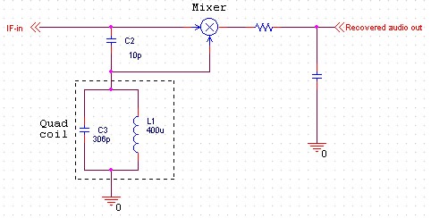 Quadrature FM detectors use a high-reactance capacitor (C2) to produce two signals with a 90 degree phase difference. The phase-shifted signal is then applied to an LC-tuned resonant at the carrier frequency (L1 and C3). Frequency changes will then produce an additional leading or lagging phase shift into the mixer.
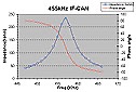
The diagram at right shows the impedance and the phase of a LC tuned circuit at 455kHz.
As you can see, the phase (red curve) is 0 at the resonans. If the frequency is lower than 455kHz then phase angle is positive and if the frequency is higher than 455kHz the phase angle is negative.
Conclution: If the frequency changes the phase will also vary and the output voltage (audio signal) to.
RULE: a multiplication of two periodic signals with the same frequency produces a DC voltage that is
directly proportional to the signal phase difference.
For small phase-shift (narrow band FM), the output will be reasonably linear.
The two most common frequency for detection is 455kHz and 10.7MHz.
For the 455kHz, you can use a (Yellow-slug) IF-can as quad-coil.
For the 10.7MHz you can use a (Green-slug) IF-can as quad-coil.
Let see what that quad coil looks like.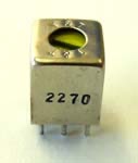
This is what the 455kHz IF can looks like.
The house is in metalic material and the core is of a ferrite material.
The yellow core can be screwed to finetune the resonans.
Sometime it can be tricky to remove the interial from the can, so be gentle.
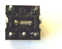
Bottom view
This is the bottom view of the can.
In the middle you can see the capacitor.
The lead from the capacitor goes up in the house and are connected to pin 1 and pin 3.
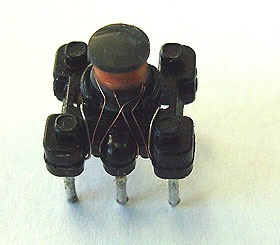
House removed
Here is the house removed.
You can see the primary winding going from pin1 to pin3. They have made a tap connetion to pin 2.
If you look close you will see the leads from the capacitor comming up (shining wire) and connect to pin1 and pin3.
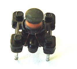
Backside of the can
This is the backside of the can.
Here you can see the secondary winding connected to pin 4 and pin 5.
